Friday, October 3, 2008

Injection Molding


Injection molding is the most commonly used manufacturing process for the fabrication of plastic parts. A wide variety of products are manufactured using injection molding, which vary greatly in their size, complexity, and application. The injection molding process requires the use of an injection molding machine, raw plastic material, and a mold. The plastic is melted in the injection molding machine and then injected into the mold, where it cools and solidifies into the final part. The steps in this process are described in greater detail in the next section.


Injection molding machine overview
Injection molding overview

Injection molding is used to produce thin-walled plastic parts for a wide variety of applications, one of the most common being plastic housings. Plastic housing is a thin-walled enclosure, often requiring many ribs and bosses on the interior. These housings are used in a variety of products including household appliances, consumer electronics, power tools, and as automotive dashboards. Other common thin-walled products include different types of open containers, such as buckets. Injection molding is also used to produce several everyday items such as toothbrushes or small plastic toys. Many medical devices, including valves and syringes, are manufactured using injection molding as well.

Capabilities

Typical Feasible
Shapes: Thin-walled: Cylindrical
Thin-walled: Cubic
Thin-walled: Complex
Flat
Part size: Envelope: 0.01 in³ - 80 ft³
Weight: 0.5 oz - 55 lb
Materials: Thermoplastics
Composites
Elastomer
Thermosets
Surface finish: 4 - 16 μin 1 - 32 μin
Tolerance: ± 0.008 in. ± 0.002 in..
Wall thickness: 0.03 - 0.25 in. 0.015 - 0.5 in.
Production quantity: 10000 - 1000000 1000 - 1000000
Lead time: Months Weeks
Advantages: Can form complex shapes and fine details
Excellent surrface finish
Good dimensional accuracy
High production rate
Low labor cost
Scrap can be recycled
Disadvantages: Limited to thin walled parts
High tooling and equipment cost
Long lead time possible
Applications: Housings, containers, caps, fittings
 

Process Cycle

The process cycle for injection molding is very short, typically between 2 seconds and 2 minutes, and consists of the following four stages:


  1. Clamping - Prior to the injection of the material into the mold, the two halves of the mold must first be securely closed by the clamping unit. Each half of the mold is attached to the injection molding machine and one half is allowed to slide. The hydraulically powered clamping unit pushes the mold halves together and exerts sufficient force to keep the mold securely closed while the material is injected. The time required to close and clamp the mold is dependent upon the machine - larger machines (those with greater clamping forces) will require more time. This time can be estimated from the dry cycle time of the machine.
  2. Injection - The raw plastic material, usually in the form of pellets, is fed into the injection molding machine, and advanced towards the mold by the injection unit. During this process, the material is melted by heat and pressure. The molten plastic is then injected into the mold very quickly and the buildup of pressure packs and holds the material. The amount of material that is injected is referred to as the shot. The injection time is difficult to calculate accurately due to the complex and changing flow of the molten plastic into the mold. However, the injection time can be estimated by the shot volume, injection pressure, and injection power.
  3. Cooling - The molten plastic that is inside the mold begins to cool as soon as it makes contact with the interior mold surfaces. As the plastic cools, it will solidify into the shape of the desired part. However, during cooling some shrinkage of the part may occur. The packing of material in the injection stage allows additional material to flow into the mold and reduce the amount of visible shrinkage. The mold can not be opened until the required cooling time has elapsed. The cooling time can be estimated from several thermodynamic properties of the plastic and the maximum wall thickness of the part.
  4. Ejection - After sufficient time has passed, the cooled part may be ejected from the mold by the ejection system, which is attached to the rear half of the mold. When the mold is opened, a mechanism is used to push the part out of the mold. Force must be applied to eject the part because during cooling the part shrinks and adheres to the mold. In order to facilitate the ejection of the part, a mold release agent can be sprayed onto the surfaces of the mold cavity prior to injection of the material. The time that is required to open the mold and eject the part can be estimated from the dry cycle time of the machine and should include time for the part to fall free of the mold. Once the part is ejected, the mold can be clamped shut for the next shot to be injected.

After the injection molding cycle, some post processing is typically required. During cooling, the material in the channels of the mold will solidify attached to the part. This excess material, along with any flash that has occurred, must be trimmed from the part, typically by using cutters. For some types of material, such as thermoplastics, the scrap material that results from this trimming can be recycled by being placed into a plastic grinder, also called regrind machines or granulators, which regrinds the scrap material into pellets. Due to some degradation of the material properties, the regrind must be mixed with raw material in the proper regrind ratio to be reused in the injection molding process.

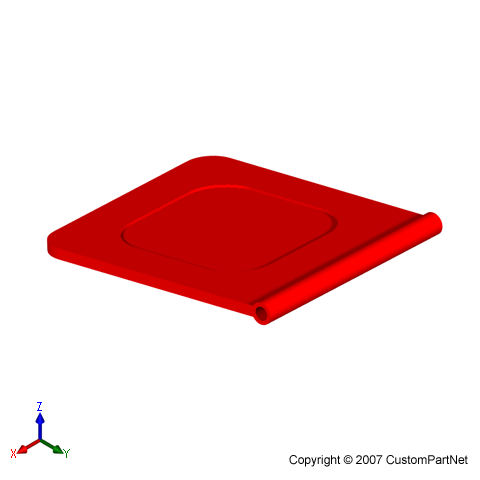
Injection molded part

Equipment

Injection molding machines have many components and are available in different configurations, including a horizontal configuration and a vertical configuration. However, regardless of their design, all injection molding machines utilize a power source, injection unit, mold assembly, and clamping unit to perform the four stages of the process cycle.


Injection unit


The injection unit is responsible for both heating and injecting the material into the mold. The first part of this unit is the hopper, a large container into which the raw plastic is poured. The hopper has an open bottom, which allows the material to feed into the barrel. The barrel contains the mechanism for heating and injecting the material into the mold. This mechanism is usually a ram injector or a reciprocating screw. A ram injector forces the material forward through a heated section with a ram or plunger that is usually hydraulically powered. Today, the more common technique is the use of a reciprocating screw. A reciprocating screw moves the material forward by both rotating and sliding axially, being powered by either a hydraulic or electric motor. The material enters the grooves of the screw from the hopper and is advanced towards the mold as the screw rotates. While it is advanced, the material is melted by pressure, friction, and additional heaters that surround the reciprocating screw. The molten plastic is then injected very quickly into the mold through the nozzle at the end of the barrel by the buildup of pressure and the forward action of the screw. This increasing pressure allows the material to be packed and forcibly held in the mold. Once the material has solidified inside the mold, the screw can retract and fill with more material for the next shot.

Injection molding machine injection unit
Injection molding machine - Injection unit

Clamping unit


Prior to the injection of the molten plastic into the mold, the two halves of the mold must first be securely closed by the clamping unit. When the mold is attached to the injection molding machine, each half is fixed to a large plate, called a platen. The front half of the mold, called the mold cavity, is mounted to a stationary platen and aligns with the nozzle of the injection unit. The rear half of the mold, called the mold core, is mounted to a movable platen, which slides along the tie bars. The hydraulically powered clamping motor actuates clamping bars that push the moveable platen towards the stationary platen and exert sufficient force to keep the mold securely closed while the material is injected and subsequently cools. After the required cooling time, the mold is then opened by the clamping motor. An ejection system, which is attached to the rear half of the mold, is actuated by the ejector bar and pushes the solidified part out of the open cavity.

Injection molding machine clamping unit
Injection molding machine - Clamping unit

Machine specifications


Injection molding machines are typically characterized by the tonnage of the clamp force they provide. The required clamp force is determined by the projected area of the parts in the mold and the pressure with which the material is injected. Therefore, a larger part will require a larger clamping force. Also, certain materials that require high injection pressures may require higher tonnage machines. The size of the part must also comply with other machine specifications, such as shot capacity, clamp stroke, minimum mold thickness, and platen size.

Injection molded parts can vary greatly in size and therefore require these measures to cover a very large range. As a result, injection molding machines are designed to each accommodate a small range of this larger spectrum of values. Sample specifications are shown below for three different models (Babyplast, Powerline, and Maxima) of injection molding machine that are manufactured by Cincinnati Milacron.

  Babyplast Powerline Maxima
Clamp force (ton) 6.6 330 4400
Shot capacity (oz.) 0.13 - 0.50 8 - 34 413 - 1054
Clamp stroke (in.) 4.33 23.6 133.8
Min. mold thickness (in.) 1.18 7.9 31.5
Platen size (in.) 2.95 x 2.95 40.55 x 40.55 122.0 x 106.3

Injection molding machine

Tooling

The injection molding process uses molds, typically made of steel or aluminum, as the custom tooling. The mold has many components, but can be split into two halves. Each half is attached inside the injection molding machine and the rear half is allowed to slide so that the mold can be opened and closed along the mold's parting line. The two main components of the mold are the mold core and the mold cavity. When the mold is closed, the space between the mold core and the mold cavity forms the part cavity, that will be filled with molten plastic to create the desired part. Multiple-cavity molds are sometimes used, in which the two mold halves form several identical part cavities.


Injection molding mold overview
Mold overview

Mold base


The mold core and mold cavity are each mounted to the mold base, which is then fixed to the platens inside the injection molding machine. The front half of the mold base includes a support plate, to which the mold cavity is attached, the sprue bushing, into which the material will flow from the nozzle, and a locating ring, in order to align the mold base with the nozzle. The rear half of the mold base includes the ejection system, to which the mold core is attached, and a support plate. When the clamping unit separates the mold halves, the ejector bar actuates the ejection system. The ejector bar pushes the ejector plate forward inside the ejector box, which in turn pushes the ejector pins into the molded part. The ejector pins push the solidified part out of the open mold cavity.

Injection molding mold base
Mold base

Mold channels


In order for the molten plastic to flow into the mold cavities, several channels are integrated into the mold design. First, the molten plastic enters the mold through the sprue. Additional channels, called runners, carry the molten plastic from the sprue to all of the cavities that must be filled. At the end of each runner, the molten plastic enters the cavity through a gate which directs the flow.. The molten plastic that solidifies inside these runners is attached to the part and must be separated after the part has been ejected from the mold. However, sometimes hot runner systems are used which independently heat the channels, allowing the contained material to be melted and detached from the part. Another type of channel that is built into the mold is cooling channels. These channels allow water to flow through the mold walls, adjacent to the cavity, and cool the molten plastic.

Injection molding mold channels
Mold channels

Mold design


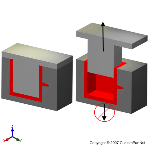
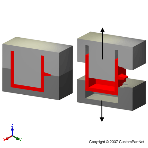
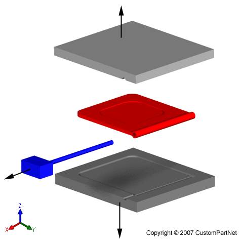
In addition to runners and gates, there are many other design issues that must be considered in the design of the molds. Firstly, the mold must allow the molten plastic to flow easily into all of the cavities. Equally important is the removal of the solidified part from the mold, so a draft angle must be applied to the mold walls. The design of the mold must also accommodate any complex features on the part, such as undercuts or threads, which will require additional mold pieces. Most of these devices slide into the part cavity through the side of the mold, and are therefore known as slides, or side-actions. The most common type of side-action is a side-core which enables an external undercut to be molded. Other devices enter through the end of the mold along the parting direction, such as internal core lifters, which can form an internal undercut. To mold threads into the part, an unscrewing device is needed, which can rotate out of the mold after the threads have been formed.

Injection molding mold
Mold - Closed

Injection molding mold exploded view
Mold - Exploded view

Materials

There are many types of materials that may be used in the injection molding process. Most polymers may be used, including all thermoplastics, some thermosets, and some elastomers. When these materials are used in the injection molding process, their raw form is usually small pellets or a fine powder. Also, colorants may be added in the process to control the color of the final part. The selection of a material for creating injection molded parts is not solely based upon the desired characteristics of the final part. While each material has different properties that will affect the strength and function of the final part, these properties also dictate the parameters used in processing these materials. Each material requires a different set of processing parameters in the injection molding process, including the injection temperature, injection pressure, mold temperature, ejection temperature, and cycle time. A comparison of some commonly used materials is shown below (Follow the links to search the material library).


Material name Abbreviation Trade names Description Applications
Acetal POM Celcon, Delrin, Hostaform, Lucel Strong, rigid, excellent fatigue resistance, excellent creep resistance, chemical resistance, moisture resistance, naturally opaque white, low/medium cost Bearings, cams, gears, handles, plumbing components, rollers, rotors, slide guides, valves
Acrylic PMMA Diakon, Oroglas, Lucite, Plexiglas Rigid, brittle, scratch resistant, transparent, optical clarity, low/medium cost Display stands, knobs, lenses, light housings, panels, reflectors, signs, shelves, trays
Acrylonitrile Butadiene Styrene ABS Cycolac, Magnum, Novodur, Terluran Strong, flexible, low mold shrinkage (tight tolerances), chemical resistance, electroplating capability, naturally opaque, low/medium cost Automotive (consoles, panels, trim, vents), boxes, gauges, housings, inhalors, toys
Cellulose Acetate CA Dexel, Cellidor, Setilithe Tough, transparent, high cost Handles, eyeglass frames
Polyamide 6 (Nylon) PA6 Akulon, Ultramid, Grilon High strength, fatigue resistance, chemical resistance, low creep, low friction, almost opaque/white, medium/high cost Bearings, bushings, gears, rollers, wheels
Polyamide 6/6 (Nylon) PA6/6 Kopa, Zytel, Radilon High strength, fatigue resistance, chemical resistance, low creep, low friction, almost opaque/white, medium/high cost Handles, levers, small housings, zip ties
Polyamide 11+12 (Nylon) PA11+12 Rilsan, Grilamid High strength, fatigue resistance, chemical resistance, low creep, low friction, almost opaque to clear, very high cost Air filters, eyeglass frames, safety masks
Polycarbonate PC Calibre, Lexan, Makrolon Very tough, temperature resistance, dimensional stability, transparent, high cost Automotive (panels, lenses, consoles), bottles, containers, housings, light covers, reflectors, safety helmets and shields
Polyester - Thermoplastic PBT, PET Celanex, Crastin, Lupox, Rynite, Valox Rigid, heat resistance, chemical resistance, medium/high cost Automotive (filters, handles, pumps), bearings, cams, electrical components (connectors, sensors), gears, housings, rollers, switches, valves
Polyether Sulphone PES Victrex, Udel Tough, very high chemical resistance, clear, very high cost Valves
Polyetheretherketon e PEEKEEK   Strong, thermal stability, chemical resistance, abrasion resistance, low moisture absorption Aircraft components, electrical connectors, pump impellers, seals
Polyetherimide PEI Ultem Heat resistance, flame resistance, transparent (amber color) Electrical components (connectors, boards, switches), covers, sheilds, surgical tools
Polyethylene - Low Density LDPE Alkathene, Escorene, Novex Lightweight, tough and flexible, excellent chemical resistance, natural waxy appearance, low cost Kitchenware, housings, covers, and containers
Polyethylene - High Density HDPE Eraclene, Hostalen, Stamylan Tough and stiff, excellent chemical resistance, natural waxy appearance, low cost Chair seats, housings, covers, and containers
Polyphenylene Oxide PPO Noryl, Thermocomp, Vamporan Tough, heat resistance, flame resistance, dimensional stability, low water absorption, electroplating capability, high cost Automotive (housings, panels), electrical components, housings, plumbing components
Polyphenylene Sulphide PPS Ryton, Fortron Very high strength, heat resistance, brown, very high cost Bearings, covers, fuel system components, guides, switches, and shields 
Polypropylene PP Novolen, Appryl, Escorene Lightweight, heat resistance, high chemical resistance, scratch resistance, natural waxy appearance, tough and stiff, low cost. Automotive (bumpers, covers, trim), bottles, caps, crates, handles, housings
Polystyrene - General purpose GPPS Lacqrene, Styron, Solarene Brittle, transparent, low cost Cosmetics packaging, pens
Polystyrene - High impact HIPS Polystyrol, Kostil, Polystar Impact strength, rigidity, toughness, dimensional stability, naturally translucent, low cost Electronic housings, food containers, toys
Polyvinyl Chloride - Plasticised PVC Welvic, Varlan Tough, flexible, flame resistance, transparent or opaque, low cost Electrical insulation, housewares, medical tubing, shoe soles, toys
Polyvinyl Chloride - Rigid UPVC Polycol, Trosiplast Tough, flexible, flame resistance, transparent or opaque, low cost Outdoor applications (drains, fittings, gutters)
Styrene Acrylonitrile SAN Luran, Arpylene, Starex Stiff, brittle, chemical resistance, heat resistance, hydrolytically stable, transparent, low cost Housewares, knobs, syringes
Thermoplastic Elastomer/Rubber TPE/R Hytrel, Santoprene, Sarlink Tough, flexible, high cost Bushings, electrical components, seals, washers

Possible Defects


Defect Causes
Flash
  • Injection pressure too high
  • Clamp force too low
Warping
  • Non-uniform cooling rate
Bubbles
  • Injection temperature too high
  • Too much moisture in material
  • Non-uniform cooling rate
Unfilled sections
  • Insufficient shot volume
  • Flow rate of material too low
Sink marks
  • Injection pressure too low
  • Non-uniform cooling rate
Ejector marks
  • Cooling time too short
  • Ejection force too high

Many of the above defects are caused by a non-uniform cooling rate. A variation in the cooling rate can be caused by non-uniform wall thickness or non-uniform mold temperature.


Design Rules

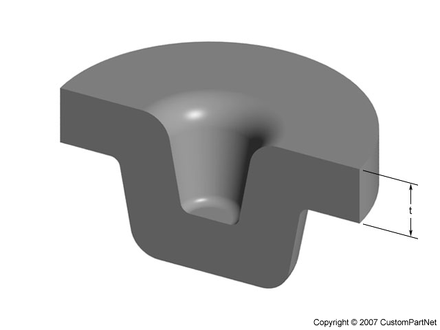
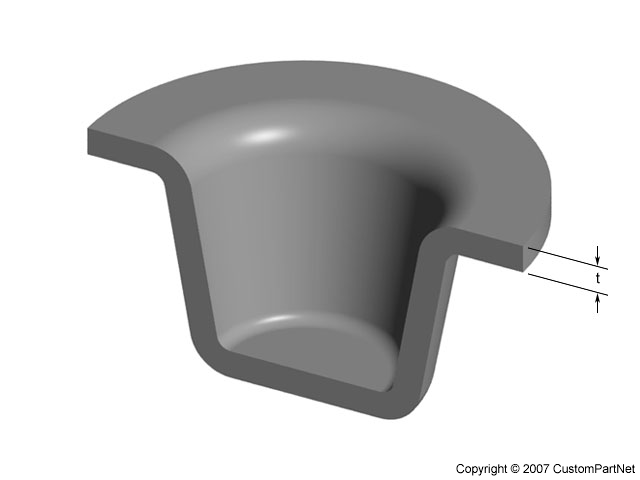
Maximum wall thickness


  • Decrease the maximum wall thickness of a part to shorten the cycle time (injection time and cooling time specifically) and reduce the part volume

INCORRECT
Part with thick walls
CORRECT
Part redesigned with thin walls

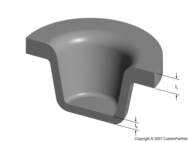
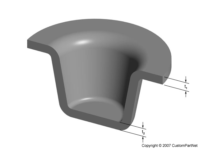
  • Uniform wall thickness will ensure uniform cooling and reduce defects

INCORRECT
Non-uniform wall thickness
Non-uniform wall thickness (t1 ≠ t2)
CORRECT
Uniform wall thickness
Uniform wall thickness (t1 = t2)

Corners


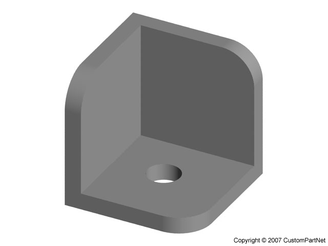
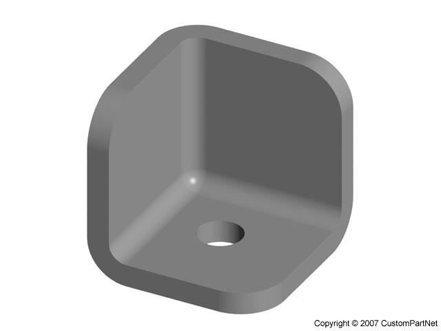
  • Round corners to reduce stress concentrations and fracture
  • Inner radius should be at least the thickness of the walls

INCORRECT
Sharp corner
Sharp corner
CORRECT
Rounded corner
Rounded corner

Draft


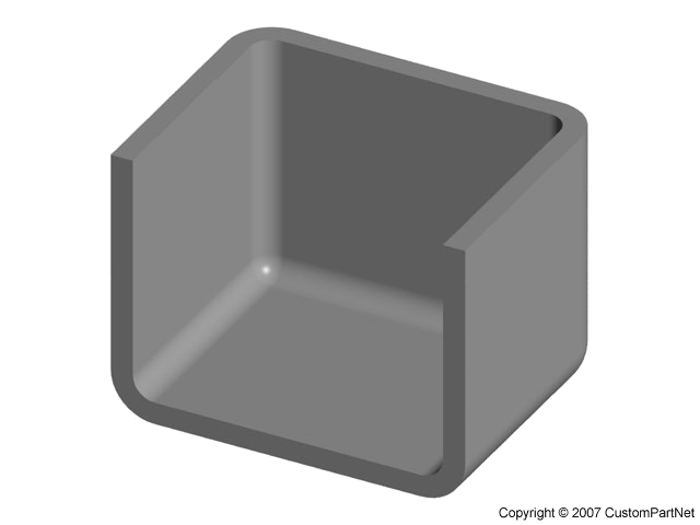
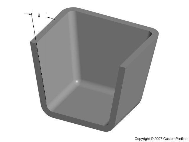
  • Apply a draft angle of 1° - 2° to all walls parallel to the parting direction to facilitate removing the part from the mold.

INCORRECT
No Draft Angle
No draft angle
CORRECT
Draft Angle
Draft angle (q)

Ribs


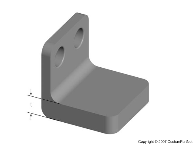
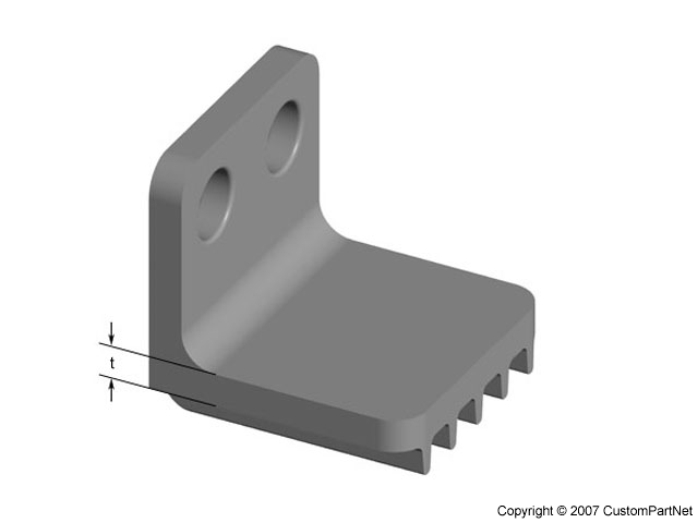
  • Add ribs for structural support, rather than increasing the wall thickness

INCORRECT

Thick wall of thickness t
CORRECT

Thin wall of thickness t with ribs

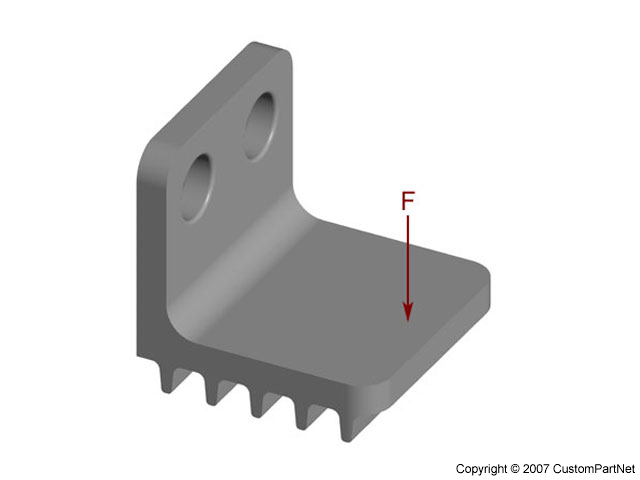
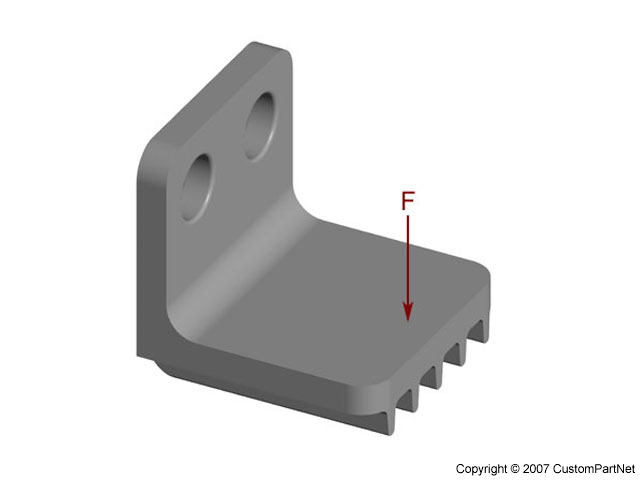
  • Orient ribs perpendicular to the axis about which bending may occur

INCORRECT

Incorrect rib direction under load F
CORRECT

Correct rib direction under load F

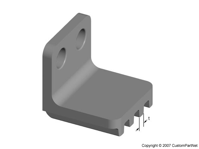
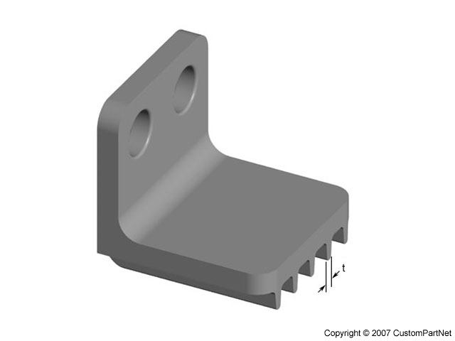
  • Thickness of ribs should be 50-60% of the walls to which they are attached
  • Height of ribs should be less than three times the wall thickness
  • Round the corners at the point of attachment
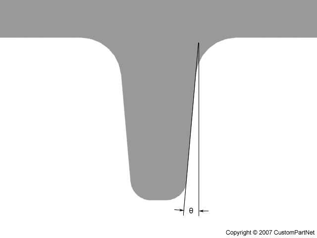
  • Apply a draft angle of at least 0.25°

INCORRECT
Thick rib of thickness t
CORRECT
Thin rib of thickness t


Close up of ribs
Close up of ribs

Bosses


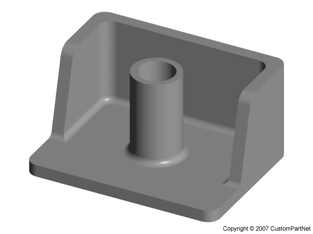
  • Wall thickness of bosses should be no more than 60% of the main wall thickness
  • Radius at the base should be at least 25% of the main wall thickness
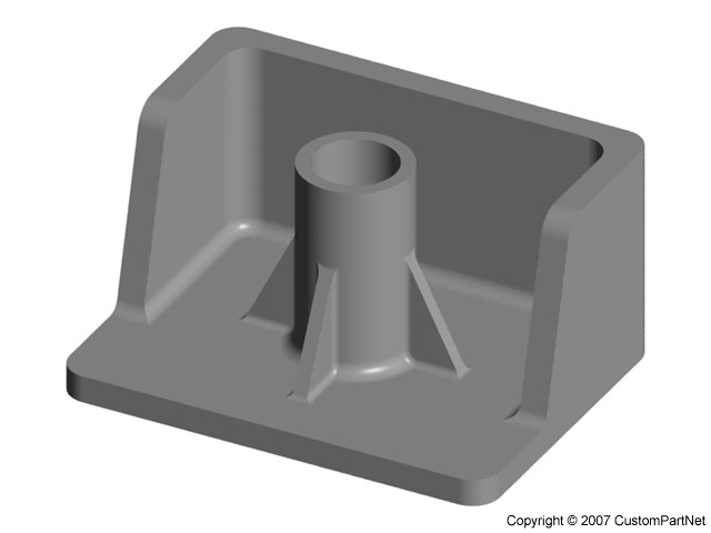
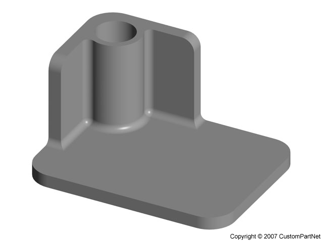
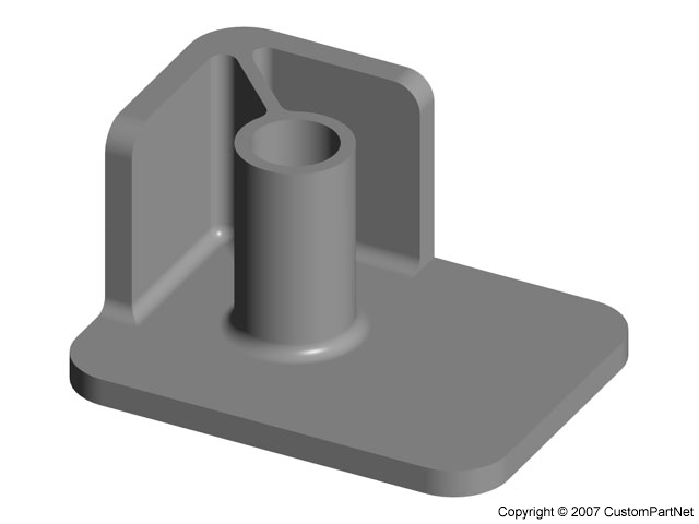
  • Should be supported by ribs that connect to adjacent walls or by gussets at the base.

INCORRECT
Isolated boss
Isolated boss
CORRECT
Isolated boss with ribs    Isolated boss with gussets
Isolated boss with ribs (left) or gussets (right)

  • If a boss must be placed near a corner, it should be isolated using ribs.

INCORRECT
Boss in corner
Boss in corner
CORRECT
Ribbed boss in corner

Undercuts


  • Minimize the number of external undercuts
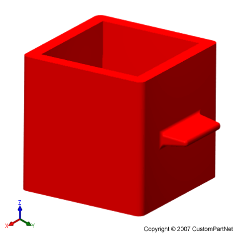
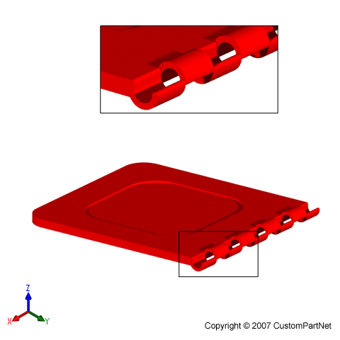
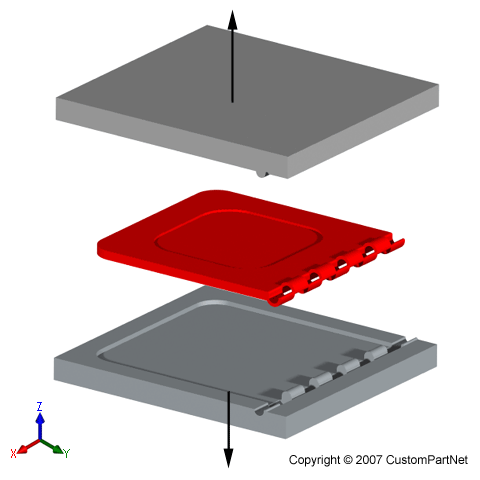
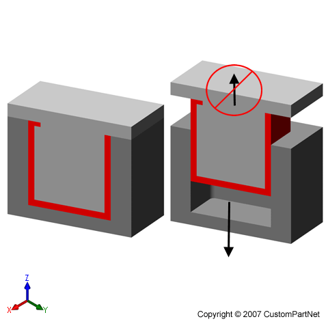
  • External undercuts require side-cores which add to the tooling cost
  • Some simple external undercuts can be molded by relocating the parting line

Simple external undercut
Mold cannot seperate
Mold cannot separate
New parting line allows undercut

  • Redesigning a feature can remove an external undercut

Part with hinge
Part with hinge
Hinge requires side-core

Redesigned hinge
Redesigned hinge
New hinge can be molded

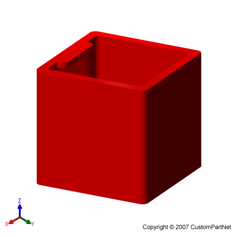
  • Minimize the number of internal undercuts
  • Internal undercuts often require internal core lifters which add to the tooling cost
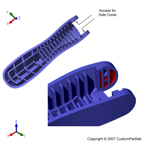
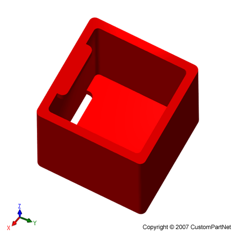
  • Designing an opening in the side of a part can allow a side-core to form an internal undercut

Internal undercut accessible from the side
Internal undercut accessible
from the side

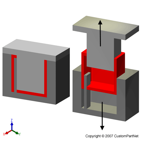
  • Redesigning a part can remove an internal undercut

Part with internal undercut
Mold cannot separate

Part redesigned with slot
New part can be molded

  • Minimize number of side-action directions
  • Additional side-action directions will limit the number of possible cavities in the mold

Threads


  • If possible, features with external threads should be oriented perpendicular to the parting direction.
  • Threaded features that are parallel to the parting direction will require an unscrewing device, which greatly adds to the tooling cost.

Cost Drivers

Material cost

The material cost is determined by the weight of material that is required and the unit price of that material. The weight of material is clearly a result of the part volume and material density; however, the part's maximum wall thickness can also play a role. The weight of material that is required includes the material that fills the channels of the mold. The size of those channels, and hence the amount of material, is largely determined by the thickness of the part.


Production cost

The production cost is primarily calculated from the hourly rate and the cycle time. The hourly rate is proportional to the size of the injection molding machine being used, so it is important to understand how the part design affects machine selection. Injection molding machines are typically referred to by the tonnage of the clamping force they provide. The required clamping force is determined by the projected area of the part and the pressure with which the material is injected. Therefore, a larger part will require a larger clamping force, and hence a more expensive machine. Also, certain materials that require high injection pressures may require higher tonnage machines. The size of the part must also comply with other machine specifications, such as clamp stroke, platen size, and shot capacity.

The cycle time can be broken down into the injection time, cooling time, and resetting time. By reducing any of these times, the production cost will be lowered. The injection time can be decreased by reducing the maximum wall thickness of the part and the part volume. The cooling time is also decreased for lower wall thicknesses, as they require less time to cool all the way through. Several thermodynamic properties of the material also affect the cooling time. Lastly, the resetting time depends on the machine size and the part size. A larger part will require larger motions from the machine to open, close, and eject the part, and a larger machine requires more time to perform these operations.
Tooling cost

The tooling cost has two main components - the mold base and the machining of the cavities. The cost of the mold base is primarily controlled by the size of the part's envelope. A larger part requires a larger, more expensive, mold base. The cost of machining the cavities is affected by nearly every aspect of the part's geometry. The primary cost driver is the size of the cavity that must be machined, measured by the projected area of the cavity (equal to the projected area of the part and projected holes) and its depth. Any other elements that will require additional machining time will add to the cost, including the feature count, parting surface, side-cores, lifters, unscrewing devices, tolerance, and surface roughness.

The quantity of parts also impacts the tooling cost. A larger production quantity will require a higher class mold that will not wear as quickly. The stronger mold material results in a higher mold base cost and more machining time.

One final consideration is the number of side-action directions, which can indirectly affect the cost. The additional cost for side-cores is determined by how many are used. However, the number of directions can restrict the number of cavities that can be included in the mold. For example, the mold for a part which requires 3 side-action directions can only contain 2 cavities. There is no direct cost added, but it is possible that the use of more cavities could provide further savings.

.

__,_._,___


Download prohibited? No problem. CHAT from any browser, without download.

TIG welding - an overview


By Marty Rice, Contributing Writer

Welding instructor Marty Rice explains the gas tungsten arc welding (GTAW) process, more commonly known as tungsten inert gas (TIG) welding.

As I've said before, I like to begin my articles by relating a personal dumb but funny learning experience. Why do I do this, you might ask?
 
Because I'm not afraid to admit I make mistakes; after all, I'm human. I've been taught by, worked for, and even been friends with a few people who think they are some kind of perfect. You know the type; it's their way or the highway. You could show them a better way, but they would still do it their way because they wouldn't dare admit that you could be right.
 
Not me. Even though I've been in the welding field a long time, I still make a mistake now and then. And sometimes I don't see a solution to a problem, even when it's staring me in the face. I'm not afraid of learning something new either. If there's a better way of doing it, bring it on!
I tell my new welding students that it's OK to make a mistake in our shop, because that's just what's going to happen when you're a "newbie." Newbie is a very affectionate term soldiers who had been there awhile called us new guys when we first arrived overseas—that, or FNG, which I think must've meant "funny new guy." What's most important with my newbies is that they learn from their mistakes, and don't repeat them.
 
A former student, Michael Salceda, now is an apprentice in the Ironworkers Union. He comes around and helps me when his work is rained out or slow. When Michael heard the story I'm about to relate, he just shook his head and said, "Mr. Rice, you should have had a pair of pliers or wire cutters in your truck." Yep, he was right; wire cutters would've saved me some pain and money.
 
My son and I bought a bike to fix up from The Motorcycle Man in Dickinson, Texas, close to Galveston. We planned to pick it up and then eat some good seafood down on the coast.
 
We found the shop and loaded the bike in my son's truck. I then pulled out the package of tie-down straps I had just bought—four tie-downs and each one had four wide, hard plastic bands around them. I popped the first band off with my pocket knife, but the next one was difficult to cut. I tried to pop it upward when it slipped and my pocket knife (did I mention I had just sharpened it?) stuck into the bone in my left inside forearm.
 
Should have left it there, but my first reaction was to jerk it out. When I did, blood shot out of my arm like a garden hose, because I had hit an artery! (Also nicked a tendon and hit muscle, but no permanent damage, thank goodness.) I applied pressure with my hand, and Bill (the Motorcycle Man) wrapped my arm in a towel and whisked me to his car for a trip to the hospital.
 
After I suppressed my urge to scream like a child, and once I realized I wasn't going to die, I thought about what a shame it was that I wouldn't get to eat some good seafood while I was in that part of Texas. (It's funny how my mind works in a crisis situation.)
But thanks to the marvels of modern medicine, I was down on the coast eating fresh oysters and having a cool one just a couple of hours later. Besides having a bruise from my hand to my elbow, I was just fine.
 
Most welders carry pocket knives. Be careful with them! I received a very painful reminder to use the right tool for the right job.
 
Before I turn this whole article into my freak accident story, here's my synopsis of the tungsten inert gas (TIG) welding process and some of the tools it requires.


Background

Some older welders still refer to TIG as "heliarc," which is what the process originally was called.
 
Heliarc was perfected around 1941 and was used to weld on magnesium, aluminum, and stainless. It was especially helpful in the war effort for welding on airplanes.
 
Heliarc used pure helium as an inert (meaning it won't combine with other elements) shielding gas to protect the weld pool from the atmosphere. (Nitrogen, hydrogen, oxygen, carbon dioxide, and other elements cause weld defects if introduced to the weld pool.)


Enter Argon

After a while it was discovered that argon has some advantages over helium. Because argon is heavier than helium, less flow rate is needed. (We use about 20 to 25 cubic feet per hour (CFH) in our shop.) The lower flow rate requirement makes argon better for flat welding. Helium is good for overhead, because it is lighter and thus flows upward.
 
Argon allows easier arc starting and a smoother, more stable arc than helium does. Actually, argon pretty much is the most widely used shielding gas nowadays.
Since the heliarc process no longer used only helium, someone decided to rename it TIG for tungsten inert gas welding.
 
Later the same guy who changed the "library" to the "learning resource center" must have decided TIG was too easy, so he named it gas tungsten arc welding (GTAW). But most everyone I know in the shop and field still call the process TIG.


Nonconsumable Electrode

TIG uses a tungsten electrode that is nonconsumable. In other words it does not burn up like an electrode in stick welding or the wire in metal inert gas (MIG) welding does. The tungsten acts as the torch: It generates heat, which melts the metal and/or filler metal.
 
Thin metals can be joined by TIG welding without using filler metal.. Joining thicker metals requires using an approximately 3-ft.-long filler rod of various diameters that is fed into the weld pool with one hand, while the torch is manipulated with the other.
 
While MIG welding is relatively easy to learn, TIG isn't. It takes a lot more skill and know-how to make a good TIG weld. One of the best ways to learn TIG welding is to learn oxygen/acetylene welding or brazing first. Although oxyacetylene welding pretty much is obsolete as a major welding process, it is perfect for learning the premise of a good TIG bead. You have to hold the TIG torch at the right angle, keep the weld pool uniform, and add the correct amount of filler metal to produce a good bead. (And, of course, relax your hand, and watch the puddle!)


A Process for All Metals

If you watch "Orange County Choppers," "Monster Garage," or some of the other fabrication shows on TV, you probably have seen chromium molybdenum steel (chromoly) bike frames TIG welded, because TIG is good for all metals. I mainly teach TIG welding on mild steel first, followed by stainless steel, and then aluminum. It also is good for copper, magnesium, titanium, nickel, and a host of others.
 
In the classroom we use a 3/32" tungsten electrode with direct current, electrode negative (DCEN) on small-gauge to 1/4-in. mild steel and stainless, then switch to alternating current (AC) on aluminum.
 
(Remember, electricity always flows from negative to positive in DC and flows back and forth on a sine wave in AC.)
 
I always used to use tungsten electrodes with 2 percent thorium until talking with someone who told me that thorium is radioactive and probably not a good substance to be touching and breathing. Avoid thoriated tungsten electrodes that can pose health and environmental risks at elevated exposure levels.


Learning TIG

For those interested in learning TIG welding, I strongly suggest that you check out a local welding school or college to find a course that offers good training in both theory and practice. Some schools will let you take specific classes to accommodate exactly what you want to learn. I know that Dewayne Roy at Mountain View College in Dallas tries to customize his classes to adults wanting to learn TIG or MIG. Perhaps you will find such a place where you live.
 
A future article will discuss TIG welding machines. If you plan to purchase one, you can expect to lay out quite a few more bucks than you would for a MIG welding machine.

Recommended TIG Welding Sites


.

__,_._,___


Did you know? You can CHAT without downloading messenger. Click here

Understanding Employee Motivation


Understanding Employee Motivation

James R.. Lindner
Research and Extension Associate
The Ohio State University
Piketon Research and Extension Center
Piketon, Ohio
Internet address: lindner.16@osu. edu
Introduction to Motivation
At one time, employees were considered just another input into the production of goods and services. What perhaps changed this way of thinking about employees was research, referred to as the Hawthorne Studies, conducted by Elton Mayo from 1924 to 1932 (Dickson, 1973). This study found employees are not motivated solely by money and employee behavior is linked to their attitudes (Dickson, 1973). The Hawthorne Studies began the human relations approach to management, whereby the needs and motivation of employees become the primary focus of managers (Bedeian, 1993).
Motivation Theories
Understanding what motivated employees and how they were motivated was the focus of many researchers following the publication of the Hawthorne Study results (Terpstra, 1979). Five major approaches that have led to our understanding of motivation are Maslow's need-hierarchy theory, Herzberg's two- factor theory, Vroom's expectancy theory, Adams' equity theory, and Skinner's reinforcement theory.
According to Maslow, employees have five levels of needs (Maslow, 1943): physiological, safety, social, ego, and self- actualizing. Maslow argued that lower level needs had to be satisfied before the next higher level need would motivate employees. Herzberg's work categorized motivation into two factors: motivators and hygienes (Herzberg, Mausner, & Snyderman, 1959). Motivator or intrinsic factors, such as achievement and recognition, produce job satisfaction. Hygiene or extrinsic factors, such as pay and job security, produce job dissatisfaction.
Vroom's theory is based on the belief that employee effort will lead to performance and performance will lead to rewards (Vroom, 1964). Rewards may be either positive or negative. The more positive the reward the more likely the employee will be highly motivated. Conversely, the more negative the reward the less likely the employee will be motivated.
Adams' theory states that employees strive for equity between themselves and other workers. Equity is achieved when the ratio of employee outcomes over inputs is equal to other employee outcomes over inputs (Adams, 1965).
Skinner's theory simply states those employees' behaviors that lead to positive outcomes will be repeated and behaviors that lead to negative outcomes will not be repeated (Skinner, 1953). Managers should positively reinforce employee behaviors that lead to positive outcomes. Managers should negatively reinforce employee behavior that leads to negative outcomes.
Motivation Defined
Many contemporary authors have also defined the concept of motivation. Motivation has been defined as: the psychological process that gives behavior purpose and direction (Kreitner, 1995); a predisposition to behave in a purposive manner to achieve specific, unmet needs (Buford, Bedeian, & Lindner, 1995); an internal drive to satisfy an unsatisfied need (Higgins, 1994); and the will to achieve (Bedeian, 1993). For this paper, motivation is operationally defined as the inner force that drives individuals to accomplish personal and organizational goals.
The Role of Motivation
Why do we need motivated employees? The answer is survival (Smith, 1994). Motivated employees are needed in our rapidly changing workplaces. Motivated employees help organizations survive. Motivated employees are more productive. To be effective, managers need to understand what motivates employees within the context of the roles they perform. Of all the functions a manager performs, motivating employees is arguably the most complex. This is due, in part, to the fact that what motivates employees changes constantly (Bowen & Radhakrishna, 1991). For example, research suggests that as employees' income increases, money becomes less of a motivator (Kovach, 1987). Also, as employees get older, interesting work becomes more of a motivator.
Purpose
The purpose of this study was to describe the importance of certain factors in motivating employees at the Piketon Research and Extension Center and Enterprise Center. Specifically, the study sought to describe the ranked importance of the following ten motivating factors: (a) job security, (b) sympathetic help with personal problems, (c) personal loyalty to employees, (d) interesting work, (e) good working conditions, (f) tactful discipline, (g) good wages, (h) promotions and growth in the organization, (i) feeling of being in on things, and (j) full appreciation of work done. A secondary purpose of the study was to compare the results of this study with the study results from other populations.
Methodology
The research design for this study employed a descriptive survey method. The target population of this study included employees at the Piketon Research and Extension Center and Enterprise Center (centers). The sample size included all 25 employees of the target population. Twenty-three of the 25 employees participated in the survey for a participation rate of 92%. The centers are in Piketon, Ohio.
The mission of the Enterprise Center is to facilitate individual and community leader awareness and provide assistance in preparing and accessing economic opportunities in southern Ohio. The Enterprise Center has three programs: alternatives in agriculture, small business development, and women's business development. The mission of the Piketon Research and Extension Center is to conduct research and educational programs designed to enhance economic development in southern Ohio. The Piketon Research and Extension Center has five programs: aquaculture, community economic development, horticulture, forestry, and soil and water resources.
From a review of literature, a survey questionnaire was developed to collect data for the study (Bowen & Radhakrishna, 1991; Harpaz, 1990; Kovach, 1987). Data was collected through use of a written questionnaire hand-delivered to participants. Questionnaires were filled out by participants and returned to an intra-departmental mailbox. The questionnaire asked participants to rank the importance of ten factors that motivated them in doing their work: 1=most important . . . 10=least important. Face and content validity for the instrument were established using two administrative and professional employees at The Ohio State University. The instrument was pilot tested with three similarly situated employees within the university. As a result of the pilot test, minor changes in word selection and instructions were made to the questionnaire.
Results and Discussion
The ranked order of motivating factors were: (a) interesting work, (b) good wages, (c) full appreciation of work done, (d) job security, (e) good working conditions, (f) promotions and growth in the organization, (g) feeling of being in on things, (h) personal loyalty to employees, (i) tactful discipline, and (j) sympathetic help with personal problems.
A comparison of these results to Maslow's need-hierarchy theory provides some interesting insight into employee motivation. The number one ranked motivator, interesting work, is a self-actualizing factor. The number two ranked motivator, good wages, is a physiological factor. The number three ranked motivator, full appreciation of work done, is an esteem factor. The number four ranked motivator, job security, is a safety factor. Therefore, according to Maslow (1943), if managers wish to address the most important motivational factor of Centers' employees, interesting work, physiological, safety, social, and esteem factors must first be satisfied. If managers wished to address the second most important motivational factor of centers' employees, good pay, increased pay would suffice. Contrary to what Maslow's theory suggests, the range of motivational factors are mixed in this study. Maslow's conclusions that lower level motivational factors must be met before ascending to the next level were not confirmed by this study.
The following example compares the highest ranked motivational factor (interesting work) to Vroom's expectancy theory. Assume that a Centers employee just attended a staff meeting where he/she learned a major emphasis would be placed on seeking additional external program funds. Additionally, employees who are successful in securing funds will be given more opportunities to explore their own research and extension interests (interesting work). Employees who do not secure additional funds will be required to work on research and extension programs identified by the director. The employee realizes that the more research he/she does regarding funding sources and the more proposals he/she writes, the greater the likelihood he/she will receive external funding.
Because the state legislature has not increased appropriations to the centers for the next two years (funds for independent research and extension projects will be scaled back), the employee sees a direct relationship between performance (obtaining external funds) and rewards (independent research and Extension projects). Further, the employee went to work for the centers, in part, because of the opportunity to conduct independent research and extension projects. The employee will be motivated if he/she is successful in obtaining external funds and given the opportunity to conduct independent research and extension projects. On the other hand, motivation will be diminished if the employee is successful in obtaining external funds and the director denies the request to conduct independent research and Extension projects.
The following example compares the third highest ranked motivational factor (full appreciation of work done) to Adams's equity theory. If an employee at the centers feels that there is a lack of appreciation for work done, as being too low relative to another employee, an inequity may exist and the employee will be dis-motivated. Further, if all the employees at the centers feel that there is a lack of appreciation for work done, inequity may exist. Adams (1965) stated employees will attempt to restore equity through various means, some of which may be counter- productive to organizational goals and objectives. For instance, employees who feel their work is not being appreciated may work less or undervalue the work of other employees.
This final example compares the two highest motivational factors to Herzberg's two-factor theory. The highest ranked motivator, interesting work, is a motivator factor. The second ranked motivator, good wages is a hygiene factor. Herzberg, Mausner, & Snyderman (1959) stated that to the degree that motivators are present in a job, motivation will occur. The absence of motivators does not lead to dissatisfaction. Further, they stated that to the degree that hygienes are absent from a job, dissatisfaction will occur. When present, hygienes prevent dissatisfaction, but do not lead to satisfaction. In our example, the lack of interesting work (motivator) for the centers' employees would not lead to dissatisfaction. Paying centers' employees lower wages (hygiene) than what they believe to be fair may lead to job dissatisfaction. Conversely, employees will be motivated when they are doing interesting work and but will not necessarily be motivated by higher pay.
The discussion above, about the ranked importance of motivational factors as related to motivational theory, is only part of the picture. The other part is how these rankings compare with related research.. A study of industrial employees, conducted by Kovach (1987), yielded the following ranked order of motivational factors: (a) interesting work, (b) full appreciation of work done, and (c) feeling of being in on things. Another study of employees, conducted by Harpaz (1990), yielded the following ranked order of motivational factors: (a) interesting work, (b) good wages, and (c) job security.
In this study and the two cited above, interesting work ranked as the most important motivational factor. Pay was not ranked as one of the most important motivational factors by Kovach (1987), but was ranked second in this research and by Harpaz (1990). Full appreciation of work done was not ranked as one of the most important motivational factors by Harpaz (1990), but was ranked second in this research and by Kovach (1987). The discrepancies in these research findings supports the idea that what motivates employees differs given the context in which the employee works. What is clear, however, is that employees rank interesting work as the most important motivational factor.
Implications for Centers and Extension
The ranked importance of motivational factors of employees at the centers provides useful information for the centers' director and employees. Knowing how to use this information in motivating centers' employees is complex. The strategy for motivating centers' employees depends on which motivation theories are used as a reference point. If Hertzberg's theory is followed, management should begin by focusing on pay and job security (hygiene factors) before focusing on interesting work and full appreciation of work done (motivator factors). If Adams' equity theory is followed, management should begin by focusing on areas where there may be perceived inequities (pay and full appreciation of work done) before focusing on interesting work and job security. If Vroom's theory is followed, management should begin by focusing on rewarding (pay and interesting work) employee effort in achieving organizational goals and objectives.
Regardless of which theory is followed, interesting work and employee pay appear to be important links to higher motivation of centers' employees. Options such as job enlargement, job enrichment, promotions, internal and external stipends, monetary, and non-monetary compensation should be considered. Job enlargement can be used (by managers) to make work more interesting (for employees) by increasing the number and variety of activities performed. Job enrichment can used to make work more interesting and increase pay by adding higher level responsibilities to a job and providing monetary compensation (raise or stipend) to employees for accepting this responsibility. These are just two examples of an infinite number of methods to increase motivation of employees at the centers. The key to motivating centers' employees is to know what motivates them and designing a motivation program based on those needs.
The results presented in this paper also have implications for the entire Cooperative Extension Sysyem. The effectiveness of Extension is dependent upon the motivation of its employees (Chesney, 1992; Buford, 1990; Smith, 1990). Knowing what motivates employees and incorporating this knowledge into the reward system will help Extension identify, recruit, employ, train, and retain a productive workforce. Motivating Extension employees requires both managers and employees working together (Buford, 1993). Extension employees must be willing to let managers know what motivates them, and managers must be willing to design reward systems that motivate employees. Survey results, like those presented here, are useful in helping Extension managers determine what motivates employees (Bowen & Radhakrishna, 1991). If properly designed reward systems are not implemented, however, employees will not be motivated.
References
Adams, J. S. (1965). Inequity in social exchange. In L. Berkowitz (ed.), Advances in experimental social psychology. New York: Academic Press.
Bedeian, A. G. (1993). Management (3rd ed.). New York: Dryden Press.
Bowen, B. E., & Radhakrishna, R. B. (1991). Job satisfaction of agricultural education faculty: A constant phenomena. Journal of Agricultural Education, 32 (2). 16-22.
Buford, J. A., Jr., Bedeian, A. G., & Lindner, J. R. (1995). Management in Extension (3rd ed.). Columbus, Ohio: Ohio State University Extension.
Buford, J. A., Jr. (1990). Extension management in the information age. Journal of Extension, 28 (1).
Buford, J. A., Jr. (1993). Be your own boss. Journal of Extension, 31 (1).
Chesney, C. E. (1992). Work force 2000: is Extension agriculture ready? Journal of Extension, 30 (2).
Dickson, W. J. (1973). Hawthorne experiments. In C. Heyel (ed.), The encyclopedia of management, 2nd ed. (pp. 298-302). New York: Van Nostrand Reinhold.
Harpaz, I. (1990). The importance of work goals: an international perspective. Journal of International Business Studies, 21. 75-93.
Herzberg, F., Mausner, B., & Snyderman, B. B. (1959). The motivation to work. New York: John Wiley & Sons.
Higgins, J. M. (1994). The management challenge (2nd ed.). New York: Macmillan.
Kovach, K. A. (1987). What motivates employees? Workers and supervisors give different answers. Business Horizons, 30. 58-65.
Kreitner, R. (1995). Management (6th ed.). Boston: Houghton Mifflin Company.
Maslow, A. H. (1943). A theory of human motivation. Psychological Review, July 1943. 370-396.
Skinner, B. F. (1953). Science and Human Behavior. New York: Free Press.
Smith, G. P. (1994). Motivation. In W. Tracey (ed.), Human resources management and development handbook (2nd ed.).
Smith, K. L. (1990). The future of leaders in Extension. Journal of Extension, 28 (1).
Terpstra, D. E. (1979). Theories of motivation: borrowing the best. Personnel Journal, 58. 376.
Vroom, V. H. (1964). Work and motivation. New York: Wiley.

This article is online at http://www.joe. org/joe/1998june /rb3.html.


_
.

__,_._,___


Did you know? You can CHAT without downloading messenger. Click here

Camshaft Design


Camshaft Design.
Camshaft design today is an extremely complex process employing the use of computers in every phase of design analysis and testing not to mention the years of experience required to make these phases become reality. As complex as it is however, camshaft design, in its simplest form, may be broken down into two segments.
The first segment involves lobe placement on the camshaft. This establishes the very critical valve train event timing in relation to piston and crankshaft positions. It also establishes the displacement or separation of the intake lobe in relation to the exhaust. This placement is very critical and must be exactly the same for each cylinder. Lobe placement is one segment of the camshaft design experience that relies heavily on the designer's experience. As you already know, you may advance or retard the camshaft in the engine, but altering the displacement requires a new camshaft.
The second segment involves designing the lobe and clearance ramp profiles. By far, this is the most critical and difficult segment of camshaft design. In today's race engines you must develop a lobe profile that is aggressive enough to produce the desired rate of lift yet smooth enough to avoid new valve train problems. You must walk a very thin line here to take advantage of the attainable high R.P.M. power available with today's cylinder head designs, yet not lose it all to stress, deflection and failure of the valve train. More recently, significant power gains have been found through several new approaches to clearance ramp profiles.
Camshaft Terminology.
Camshaft terminology can sometimes become very confusing. The diagram below should help to explain some of the terms used in the design and selection of camshafts.
 
  1. Max Lift or Nose
  2. Flank
  3. Opening Clearance Ramp
  4. Closing Clearance Ramp
  5. Base Circle
  6. Exhaust Opening Timing Figure
  7. Exhaust Closing Timing Figure
  8. Intake Opening Timing Figure
  9. Intake Closing Timing Figure
  10. Intake to Exhaust Lobe Separation
 

.

__,_._,___


Connect with friends all over the world. Get Yahoo! India Messenger.

Quality Control: How To Respond To "Just Give Me a Dashboard!"


Quality Control: How To Respond To "Just Give Me a Dashboard!"

Buzzwords such as "dashboard" are currently exerting a great deal of attraction for my clients. Most everyone who's working to improve their company's performance management systems (which Gartner refers to as corporate performance management, CPM, rather than BPM) seems to be considering implementing data visualization tools that show, at a glance, how well the organization is meeting its goals. The IT and business communities are well aware of these technologies and expect great results from them. But many companies put too little thought into the development of dashboards.
 
Although the business value of displaying key performance indicators (KPIs) in a dashboard format is widely accepted, the circumstances under which such a tool delivers the most value are not widely understood. Vendors make the problem worse by promising results in just hours or days. Clients considering buying or building dashboards frequently say to me, "I need a quick way of presenting strategic performance indicators for my top management." The demand by business managers to receive a dashboard -- any dashboard -- as quickly as possible is often shortsighted and counterproductive. But the request provides an opportunity to get it done right.
Finance and IT must argue against moving forward with incomplete, poorly considered dashboard initiatives because the failure of such a project could harm the prospects for future business intelligence and CPM efforts. They must be prepared to redirect the "Just give me a dashboard!" demand into a more constructive discussion.

Learning From the Past

The demand for better management information hasn't changed much over the past two decades. In the 1980s, executive information systems (EISs) attained great popularity by promising to meet executives' need for accurate data about the performance of the business. Unfortunately, most EIS systems failed because their maintenance was too expensive to justify for the relatively small number of users who valued the information they provided. Their usefulness was limited because they were not integrated with the company's other reporting streams. Management viewed them as offering just one more set of data that had to be reconciled with other metrics and observations. As a consequence, these systems seemed to complicate matters, rather than providing clarity for decision-making.
The business need for quality information hasn't changed appreciably since EISs were popular, but two circumstances today boost dashboards' value. First, the business case for dashboards is easier to make. The technology required for a dashboard is much less expensive than EISs were, and today's dashboards are much easier to deploy to a large number of users, which mitigates the risk of running a pilot project. Second, dashboards today have the potential to truly simplify information for senior management, instead of adding to the confusion. The methodologies for managing performance are much clearer; they include the Balanced Scorecard, Six Sigma, and activity-based management. These concepts help companies identify the metrics executives actually need and avoid inundating them with information they don't need.

Setting the Right Scope

Unfortunately, the failure of EISs 15 years ago seems to be far from the minds of managers demanding dashboard solutions today. Most of those who lived through the EIS craze have forgotten the lessons learned, and younger managers were never exposed to them. Inquiries about today's dashboards sound very similar to requests for EIS systems two decades ago. The wrong response from finance and IT could doom a dashboard to the same fate as its predecessors.
One problem with many dashboard projects is that although executives ask for a "strategic" tool, they also want it to be "simple" -- and they want it immediately. They usually allot a very small budget to the project, as well, because they don't want to fund an expensive business intelligence initiative that may not generate ROI. This attitude leads to a misalignment between expectations that are high and strategic in nature and results that are limited and tactical. Another common problem is that executives seek individual metrics that seem important, rather than developing a system of metrics in a complete Balanced Scorecard framework or strategy map. Managers who are impatient with the timeline required to design a quality dashboard end up with metrics that don't present a clear picture of corporate progress.
In addition, many dashboard project managers avoid sharing results with the broader management team and keep costs to a minimum so that they can sail along below the organization' s radar screen. This is a valid strategy for initially testing the applicability of the dashboard concept, but if the initiative doesn't graduate beyond a "proof of concept" style project, the resulting system will not provide optimal performance. Companies focused on implementing the fastest and cheapest solution possible are not helped by CPM software vendors that encourage use of their products to complete a dashboard within a week or to choose KPIs within a few hours.

Defending Against Misguided Managers

Even when senior managers approach dashboards with skewed expectations, finance and IT staff should embrace their desire for such a system. A request for a dashboard is a sign that executives realize they need better management information. The resulting project can be an excellent test of which corporate data is readily available at high quality and which data is entered manually and fragmented. The project team can use a strategy map to evaluate how complete and predictive a company's management information is. In that sense, the dashboard initiative itself can function as a performance indicator by showing the auditability, speed, quality, and alignment of the information that's reported to top management.
Assuming that some trouble spots appear in the review of the quality of management data, the dashboard development process should include the following activities:
Properly define corporate metrics. Defining the right metrics is a collaborative process, and the discussions it entails can lead to a common understanding companywide about which KPIs are most important and how they relate to one another. The process starts with the executive team clarifying corporate strategy, determining the contribution that business units will make to that strategy, assigning project "owners" to supervise performance, and agreeing on a set of KPIs. But executives' definitions of metrics should allow room for clarification and refinement. Metrics shouldn't be imposed from the top down, either by management or by outside experts. That's a recipe for setting unrealistic targets, which almost always leads to failure because staff will find ways to evade performance measures they oppose. In contrast, when all of an organization' s stakeholders engage in a collaborative process that is initiated and led by management, then facilitated by a project team, they create conditions favorable to operational alignment throughout the company. And, after all, operational alignment is one of the objectives of a management dashboard.
Over time, companies should improve on their first set of metrics, refining the KPIs through a process I compare to peeling an onion, so that they eventually reach the core of the matter. Metrics that are not linked to objectives -- and objectives that are not linked to strategy -- are not useful. The groundwork required to select the right set of metrics is an integral part of any dashboard implementation project.
Consider metrics holistically to ensure you've selected the right ones. Organizations that don't use a framework such as the Balanced Scorecard to make sure their set of metrics is coherent can't expect to achieve value other than anecdotal indications of performance. To be predictive, metrics must be considered in the context of a strategy map, a cause-and-effect diagram of the relationships among objectives -- or, at a level of greater detail, among KPIs. Without a strategy map, a dashboard is nothing more than a means of visualizing uncoordinated metrics.
Give data management as much attention as it needs. Dashboards are always easier to create for companies that have already implemented a solid data warehouse infrastructure. This simplifies the integration of the needed data and its aggregation to the relevant levels. The dashboard is, after all, nothing more than the most aggregated level of corporate data.
Some vendors' software demos assume that customers have a good grasp of the KPIs that would be most beneficial to their business and that all the necessary data is already available and is both integrated and cleansed. This is seldom the case. Eighty percent of the effort behind most scorecard or dashboard initiatives consists of defining the metrics and finding the right data. In this regard, the lack of a budget for a dashboard initiative can actually work to a project team's advantage. Low funding may direct attention to the organization' s need for a comprehensive business intelligence and data warehousing strategy. The result of an effective business intelligence strategy is that the top layer -- the performance indicators in a dashboard -- can be automatically derived from the lower levels of information that the company already has available. All of the necessary data is there; the dashboard project simply aggregates it to one more level.
Gain the buy-in of managers throughout the company. The support of middle managers is crucial for translating a CPM strategy into action. The people in this layer of the organizational chart are responsible for the activities that bring corporate strategy to life. In my experience, whenever a CPM data-visualization tool provides basic drill-down capabilities, usage at the middle-management level takes off. The drill-down of KPIs into relevant breakouts provides tactical information that convinces middle management of the dashboard's value.
Yet middle management is often the group within a company that most actively resists CPM.. Business managers frequently fear that new reporting mechanisms will somehow expose them or threaten their power. One strategy for obtaining their buy-in is to cite the pressures that surround corporate compliance audits. Sarbanes-Oxley provides plenty of justification for simplifying reporting streams into "one version of the truth." Dashboard project leaders can also put the matter to managers in a more positive light by building a business case for sharing management data with many different stakeholders. Before the organization can assemble such information, all contributors of corporate performance data will have to examine their processes and develop controls to ensure that the information is accurate and timely.
Putting together a top-quality performance management dashboard isn't easy. Managers often expect a new tool to be a panacea, when technology actually is the least of their problems. The key to success is strategic alignment -- one version of the truth, with dashboards thoroughly integrated into management processes. The best dashboards are free; they're nothing more than the last step of aggregation of a well-defined set of metrics and management reports. If management demands a dashboard, treat it as a chance to pursue a complete business intelligence strategy.
Frank Buytendijk is vice president of corporate strategy for Hyperion. He helps drive strategic direction for Hyperion worldwide. Before joining Hyperion in early 2006, Buytendijk was a research vice president with Gartner.
 

.

__,_._,___


Be the first one to try the new Messenger 9 Beta! Click here.

Time & Motion Studies


Time & Motion Studies

The idea of a Time and Motion Study is often still associated with production lines and manufacturing industry. It gained a bad reputation as a source of disagreement between "management" and "workers". However if used properly it can be of benefit to modern companies and their workforce.
This is a massive field - what follows is a brief overview.
Factory Life
Factory Life in 1898

History

Scientific Management

Time and Motion studes have their roots in the work of Frederick Winslow Taylor who in 1911 published his famous article "The Principles of Scientific Management". Essentially this involved getting the best person for each job and training them to do it the best way possible. Although Taylor believed in cooperation between management and workers, "Taylorism" can be seen as formalising the management/worker divide. Management would be responsible for deciding how things were done with workers simply doing what they were told. It was seen as dehumanising, reducing skilled workers to the status of mechanical parts and resources.

Gilbreths

Time and Motion study was refined in the early twentieth century by Frank and Lillian Gilbreth. The Gilbreths' preferred "motion study" to Taylor's "time study", however the term "Time and Motion" has tended to stick in popular terminology.
The Gilbreths studied the actions taken by workers at certain task with the aim of streamlining the processes involved. One of their most famous experiments involved analysing the work of bricklayers and significantly reducing the number of "operations" involved. This change benefited both employer (increased productivity) and employee (decreased fatigue).

Therbligs

The Gilbreths developed a categorisation system for the different basic activities which went to make up a task. These were called Therbligs (an anagram of "Gilbreths") . The basic Therbligs numbered around 15 (the system developed over time) and included such actions as "find", "select" and "rest". Each of these was represented by an icon, for example an eye for "find". The activity of a worker could then be plotted on a Simo Chart ("Simultaneous Motion Chart") for optimisation.
 

Hawthorne Effect

One problem for Time and Motion studies is what is known as the Hawthorne Effect (named after a factory not a person). This in essence says that employees change their behaviour when they know that they are being measured - the mere act of performing a study can improve performance. It's a form of "observer effect" akin to a productivity placebo.
The Hawthorne Effect also showed that productivity tends to improve whatever changes are made, then return to normal over time. This recognises that workers are human beings and that knowing they are valued can in itself inspire better performance.
The Hawthorne Effect doesn't undermine the value of Time and Motion studies but does emphasise that people are the most significant element of any workplace.
 

MTM

The original Time and Motion Study concepts led during the twentieth century to the development of Predetermined Motion Time Systems (PMTS) such as Methods-Time- Measurement (MTM). This was released in 1948 by Maynard, Stegemerten, & Schwab and is today found in three versions: MTM-1, MTM-2 and MTM-3

Mutual Benefits

In the"bad old days" of industrial relations, Time and Motion studies were often seen as a tool for the management to exploit the workers. The Time and Motion study - sometimes carried out in secret - could be used to pressurise people to work harder or lose their jobs. It's not surprising that many workers came to resent the whole concept of time & motion.
It needn't be that way. Modern analysis methodologies and software packages have little in common with the old image of a "Motion Man" timing workers with a stopwatch. A Time and Motion study carried out openly with full buy-in from all concerned can be of mutual benefit. Improvements can be made to working conditions and methods that both improve productivity and make working less stressful or reduce fatigue.
Perhaps the best way to ensure full cooperation is to ensure that any benefits of the study are shared between company and workforce. If efficiency improvements are identified then the gains can be shared between shareholders and workers, with the latter benefiting from greater wages or shorter hours.
Unfortunately too many companies today still see a Time and Motion study as simply a way to increase profits with no benefit returning to the workforce who are ultimately responsible for those profits.
 

.

__,_._,___


Be the first one to try the new Messenger 9 Beta! Click here.